 |
| The red line in the map above follows my travel route where I did my the measurements |
Tuesday, October 29, 2013
I measured radioactivity during my vacation in Japan, Fukushima.
Last week I came back from Japan. During my vacation trip I've logged radiation data using my Geiger counter. I have gathered samples at various places at Tokyo (including Tokyu Disneyland), Narita Airport From/To Tokyo, Tokyo From/To Osaka, Osaka From / To Hiroshima. See my travel map below:
My measuring.....
Sunday, July 28, 2013
123d beta 9 is not 123d designer, alternatives?
In my exploration in 3D modelling last year 2012, I've researched for a good CAD program below 1000$. It seemed that there are a lot of options like SketchUp, Autodesk, Alibre, FreeCad, and a lot more. Since I'm an EE, I mostly build simple and small cases or structures for electronics. Usually simple structures below 5x5x5cm's.
I've started with SketchUp (Free), moved on to Alibre (paid, below 1000$), then Autodesk 123d (free) beta 9 and now Cubify Invent (50$).
Please note that I'm using the applications for hobby usage only.
So my time is limited to just several hours a week. I'm sure with certain applications you can make the best objects if you master the application thoroughly, however, I'm more looking for a quick fix where the application can be productive the very first few hours.I've started with SketchUp (Free), moved on to Alibre (paid, below 1000$), then Autodesk 123d (free) beta 9 and now Cubify Invent (50$).
Sunday, June 9, 2013
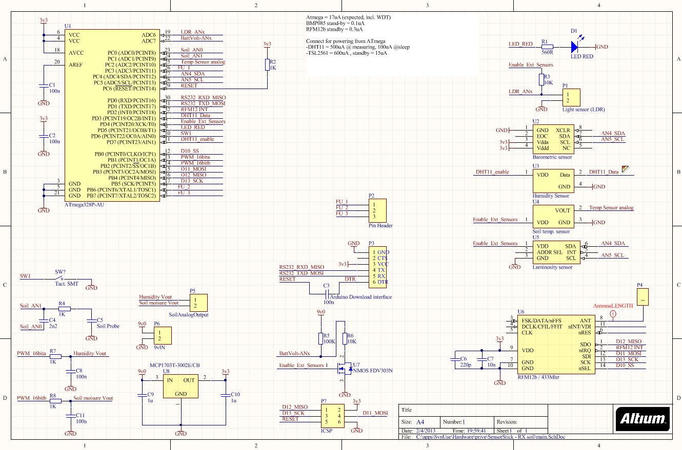
Measuring power from my solarpanels
Today I finally had some spare hours to do the following; measure the DC voltage and current from my solar panels (2 pieces, total 380 watt peak) and convert this into power. That way I can finally see how much is actually generated by the solar panels.
I used an Arduino, adapted my Wireless Garden SensorStick and attached it to a rail-to-rail OpAmp from Microchip....

Monday, April 22, 2013
Dimming TFT screen brightness - LG LED screens
LG-E2242 - 55cm / 22inch LED LCD Monitor
This screen uses LED edge lights for screen illumination. It consists of 4 strings LEDs, each string working at ~49 volts, 60mA/~3 Watts (100% brightness). All strings together uses 240mA/12 Watts. PWM is used for brightness control, setting brightness to 0% equals in 30% PWM duty cycle (~20mA avg).
This monitor contains a chip from Novatek NT68652UFG 1153-BB. There is unfortunately very little documentation found about this "all in one" chip.
 |
| LG LED monitor |
This monitor contains a chip from Novatek NT68652UFG 1153-BB. There is unfortunately very little documentation found about this "all in one" chip.
Sunday, April 21, 2013
Soldering qfn accelerometer to a breadboard friendly shape
For quick prototyping, I soldered wires to my Freescale accelerometer on a proto board. Used mini copper wires from inner core of flexible wire. See the picture attached for the results.
Saturday, April 20, 2013
Arduino nano running at 3.3volts
An easy change to your arduino nano to run it at 3.3 volts is to use the microchip MCP1700 voltage regulator. See the picture attached were the it is mounted on the bottom arduino nano.

Tuesday, April 2, 2013
Monday, April 1, 2013
Battery options
For my SensorStick I need at least 3 volts since the DHT11 only works from 3v0, all of the other sensors can work with lower voltage. A single coin cell will not be suffice since the voltage curve of such a cell decreases a little on the longer run.
This is my target for the sensor stick:
So here are my options
This is my target for the sensor stick:
- Runs at 3.3 volts using low quiescent regulator
- Uses an average current of 50uA
- Should run on battery for at least a year
At 50uA power usage and running for a year we need a battery that has: 50uAh*24hours*365years= 438mAh. So at least 438mAh is needed. Please note the battery internal drain, so we need more than calculated.
So here are my options
- 4x coin cell CR2032
- 6v
- 440mAh
- Small size, but consumes lot of space on PCB since it must be directly/flat attached to pcb
- 2x Double coin cell holders will cost 1.80euro @Digikey, BH800S
- Boost converter
- single cell from 1.5v would work (AAA)
- increased component/PCB cost, around 3 euro
- increased sleep current
- increased noise for the capacitance measurements
- Not an option due price tag.
- 3x AAA batteries
- 4.5volts
- 700mAh
- Alkaline cells has higher voltage drop in voltage curve than coin cells
- PCB mounts cost total 1.30 euro (BK-82 @digikey)
- Seperate AAA holder box cost around 50 eurocent @ebay
- 9v block
- 9volts
- 900mAh
- Higher voltage drop, just like AAA. But since it is 9 volts battery, we have a high margin.
- Consumes a lot of space.
- Battery snap-on wire cost 20 cent @ digikey
- Battery holder 60cents @ ebay or 1 euro @digikey
Putting all the things together, I currently think it is best to use the 9 volt block with snap-on wire.
Saturday, March 30, 2013
Vegetable sensor stick
Prototype setup done!
These are the sensors that I've been experimenting with on my breadboard:
- Air humidity and temperature
- DHT11
- Soil moisture using capacitance measurements
- Internal uC
- Barometer
- BMP085
- Color and amount of Light
- ADJD-S311-CR999


I've successfully gathered a week of data to the online graphing service of Cosm (internet of things / Cloud service).

You can see the day/night rhythm, and since we are still in the winter here in Netherlands, there isn't much bright daylight. Also the humidity indicator shows when I mounted the clear plastic cap over my vegetables, it caused a rapid increase of the humidity.
Please note that in the image above, the SoilMoisure, SoilTemperature and CO2 was still under development. That's why there is no (complete) line. See the complete, real-time data here https://cosm.com/feeds/119538.
Now it is time to move the prototype to the next level. I want to make a PCB out of it. Since I've currently got 10 places I want to monitor, I want to keep the costs for each unit low but very flexible/universal.
I am thinking about
The very basic version of the PCB should have at least the Soil moisture measurements for less than 15 euro. Lets see if I can keep that thought. Also thinking of a good name for the project, hmmm.. Vegetable SensorStick ? EEO SensorStick? Well.. that is for later. First make the PCB :)
Idea for the DAC output of the soil and humidity outputs


Personal note:

You can see the day/night rhythm, and since we are still in the winter here in Netherlands, there isn't much bright daylight. Also the humidity indicator shows when I mounted the clear plastic cap over my vegetables, it caused a rapid increase of the humidity.
Please note that in the image above, the SoilMoisure, SoilTemperature and CO2 was still under development. That's why there is no (complete) line. See the complete, real-time data here https://cosm.com/feeds/119538.
Making it more serious
Now it is time to move the prototype to the next level. I want to make a PCB out of it. Since I've currently got 10 places I want to monitor, I want to keep the costs for each unit low but very flexible/universal.
I am thinking about
- Battery powered (3xAAA or 1x CR2032 coin cell)
- Soil moisture area directly mounted on the PCB
- All the sensors currently attached to the PCB
- Have a voltage output that represents the value of the soil and humidity
- analog output between [0v...3v] for soil moisure (at least 12bit resolution)
- analog output between [0v...3v] for humidity (at least 8bit resolution)
- Have a serial output pins that broadcast data
- Keep the Arduino bootloader so it will be very easy for others to make changes
- but to save costs, remove the USB to UART.
- Publish source and hardware to google project as open source
- Capacitance button to pair the device to the mainboard
- LDR for light measurement for cheaper versions (PCB will be AND not OR)
The very basic version of the PCB should have at least the Soil moisture measurements for less than 15 euro. Lets see if I can keep that thought. Also thinking of a good name for the project, hmmm.. Vegetable SensorStick ? EEO SensorStick? Well.. that is for later. First make the PCB :)
Idea for the DAC output of the soil and humidity outputs

Today taken pictures of the Propagator


Personal note:
- CO2
- Humidity
- Temp Ambient
- Temp Soil
- Soil moisture
- Barometer
- Light resistor
- Color / light sensor
Thursday, March 28, 2013
Arduino capacitance measurement
I`m in the need to measure my plants soil moisture. I've read a lot about the possible options to measure soil moisture like sensing resistance or capacitance. Using the resistance measurement, the probes are sensitive to corrosion due electrolyse so I want to give it a go to measure the capacitance and see what happens.
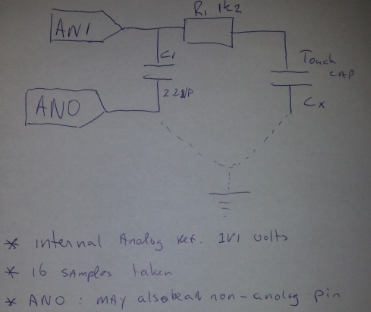
Here is what I did for the hardware part on my Arduino nano:

This is the sketch I used
#include
// analog defines
// defines for setting and clearing register bits
#ifndef cbi
#define cbi(sfr, bit) (_SFR_BYTE(sfr) &= ~_BV(bit))
#endif
#ifndef sbi
#define sbi(sfr, bit) (_SFR_BYTE(sfr) |= _BV(bit))
#endif
void setup() {
Serial.begin(9600);
Serial.println("StartUp\n");
// analog init
analogReference(INTERNAL);
// set prescale to 16
sbi(ADCSRA,ADPS2) ;
cbi(ADCSRA,ADPS1) ;
cbi(ADCSRA,ADPS0) ;
Serial.println("Init OK \n");
}
void capMeasurement(void)
{
uint16_t sensorValue = 0; // variable to store the value coming from the sensor
static uint16_t sensorHistory;
sensorValue = 0;
for(int count = 16; count != 0; count--)
{
// note that default Wire.h was to slow to use, so these are direct MCU commands.
// should make a Arduino library from it.
//pinMode(A0, OUTPUT);
//pinMode(A1, OUTPUT);
// the above commented text is done with direct MCU register commands (faster)
DDRC = DDRC | ~B11111100; // make A0/A1 output
//digitalWrite(A0, HIGH);
//digitalWrite(A1, HIGH);
// the above commented text is done with direct MCU register commands (faster)
PORTC = PORTC | B00000011; //charge external Cx
delayMicroseconds(10); // let the Cx charge 10uS
//pinMode(A1, INPUT);
DDRC = DDRC & B11111101; // make A1 input
//digitalWrite(A0, LOW);
PORTC = PORTC & B11111100; // transfer charge to C1 (by grounding C1)
// read the value from the sensor:
sensorValue += analogRead(A1);
}
PORTC = PORTC | ~B11111100; // done
Serial.print(" cap=");
Serial.print(sensorValue);
}
void loop() {
capMeasurement();
Serial.println();
}
Sunday, March 24, 2013
Arduino Nano atmega328p low power usage (sleep, etc)
Power usage Arduino Nano w/ Mega328p
*Please note, having the MK2 programmer connected = + 20uA
*Please note, I`m using cheap china multimeter.
3400uA @
-removed 7805 lin. psu
-mega running at ext. clock (original bootloader / fuses Arduino Nano)
680uA @ conditions:
-removed 7805 lin. psu
-mega running at ext. clock (original bootloader / fuses Arduino Nano)
-USB not connected.
-PSU @ 4.8vDC
-mega: set_sleep_mode(SLEEP_MODE_PWR_DOWN);
186uA @ conditions
-PSU @ 4.8vDC
-mega: set_sleep_mode(SLEEP_MODE_PWR_DOWN);
Ayyy.. time is up for today, wife is calling me... to be continued eh.. :)
Measuring growing vegetables with internet of things...
I started to measure environment variables like; temperature, barometer, hygrometer, light brightness, dominant colors and much more and report it online.
Here you can see my real-time demo: https://cosm.com/users/willyp. Please note that there are moments that I am upgrading the devices. Today I am starting to make the setup more suitable for battery operation. I`m implementing processor sleep functions and disabling external devices to conserve energy. I want to have the sensor transmitter working on a double CR2032 battery for at least a year long.

Currently in the unit there are tomatoes, paprika, carrots and beans.
I am still alive!
Wow, I looked at my blogspot account and mentioned that my last blog was over 2 years ago already!!!
Looked back at the last two years, I've got quite a lot of reasons why I did not post anymore to this blog: I really had no time left to do that!. Past years, I've lost my dad, bought a new home (and completely changed it), finished my study and much more.
But since some time I had some spare time left in the weekends so I started to pickup my hobbies again... :) .
I'will keep you posted!
By the way, I finished my KeaDrone project. It has changed a bit from helicopter to a Quadcopter design but I have it flying!! :D Already have some great pictures taken with the copter from some altitude..... :D
Subscribe to:
Comments (Atom)